Please direct any comments to: george@treefalling.com.
For a printable version (rough draft) use this link: chain_sharpening.pdf (713KB)
As a start, I describe use of the Granberg 106B filing jig to quickly achieve effectively perfectly filed chainsaw chain.
With the Granberg jig you can sharpen all chain used on hand held chainsaws. Once learned, the method is no more difficult than brushing ones teeth.
2) Flat-filed, chisel chain, also called full chisel chain, is universally recognized by experts as the fastest cutting chain. I will show you how to sharpen this type of chain on the Granberg jig as well as the other types of chain.
3) How to file in a comfortable sitting position so you can file during little breaks.
4) Simple changes to the jig to improve accuracy and speed.
5) Setting the depth gauges with the Granberg jig.
The ATOP file guide is a specialized tool for flat-filed chisel chain. It is very expensive at about $200. It does not have chain clamps so the chain may tend to roll. It does not have a file stop so you cannot control cutter length. It does not have direct control of the swivel angle or direct control of file height, although the little “rolling pin” out-rigger helps somewhat relative to hand filing. This specialized tool will not do any cutter types except flat-filed. The ATOP will not do depth gauges. The manufacture admits that ATOP cannot be used independently of a special and expensive square cutter grinder. Their plan is that you grind the chain and then the ATOP can do a few touch ups. The chain is expected to deteriorate with each touch up. Then you have to grind again, so that would be at least once per day of work. In contrast, you need no tool other than the Granberg jig to maintain your chain in top condition.
The place to start with the Granberg jig is the Granberg File-N-Joint instruction manual. I will try to name parts in accord with the Granberg parts list.
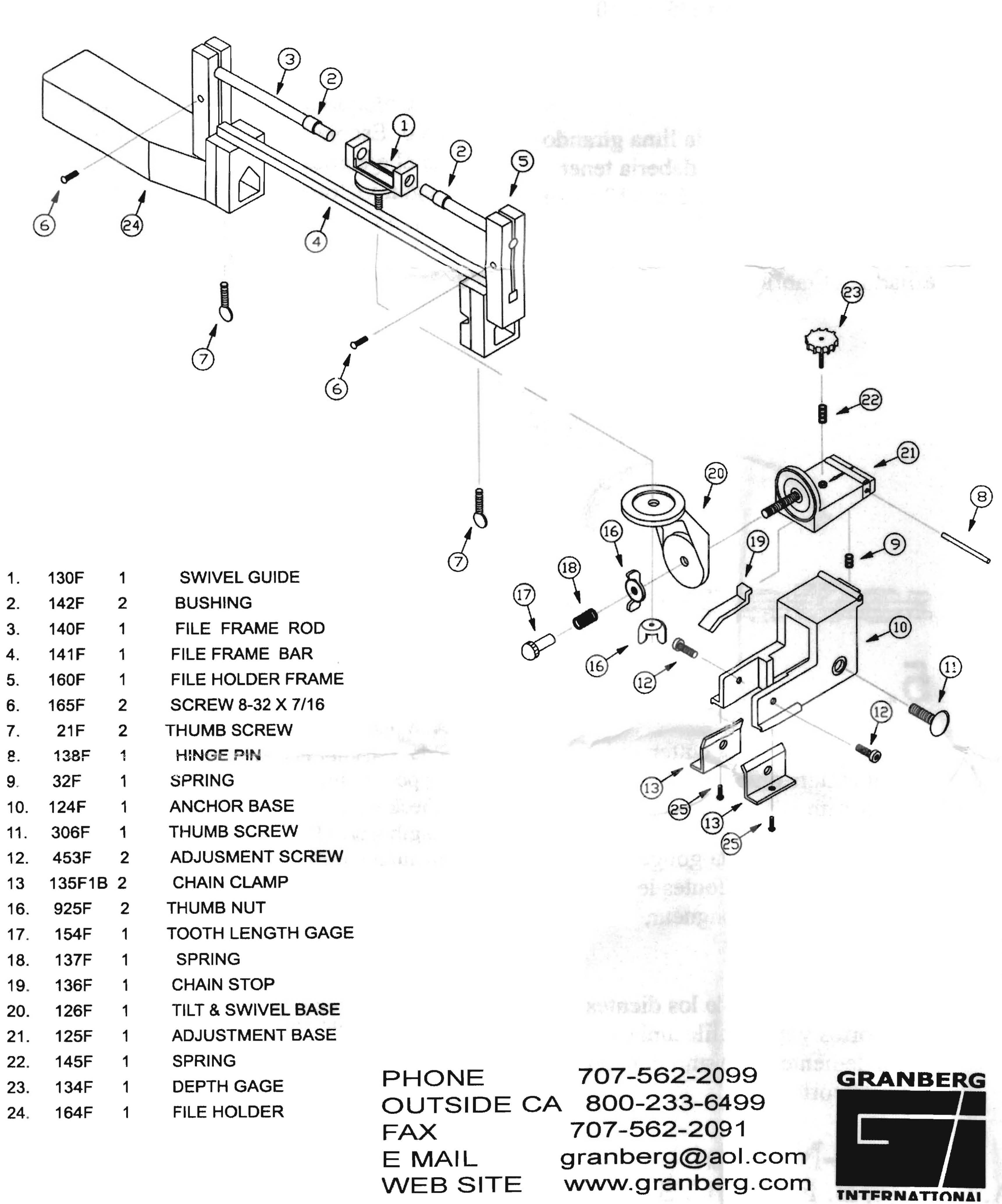
Here is the parts diagram for the Granberg jig. I will attempt to refer to the part by the names and sometimes the number as shown.
|
|
| Granberg's parts diagram. |
For round-filed chisel chain, the tilt angle is usually going to be 10 degrees. The swivel angle will usually be 25 or 30 degrees depending on the manufacturer.
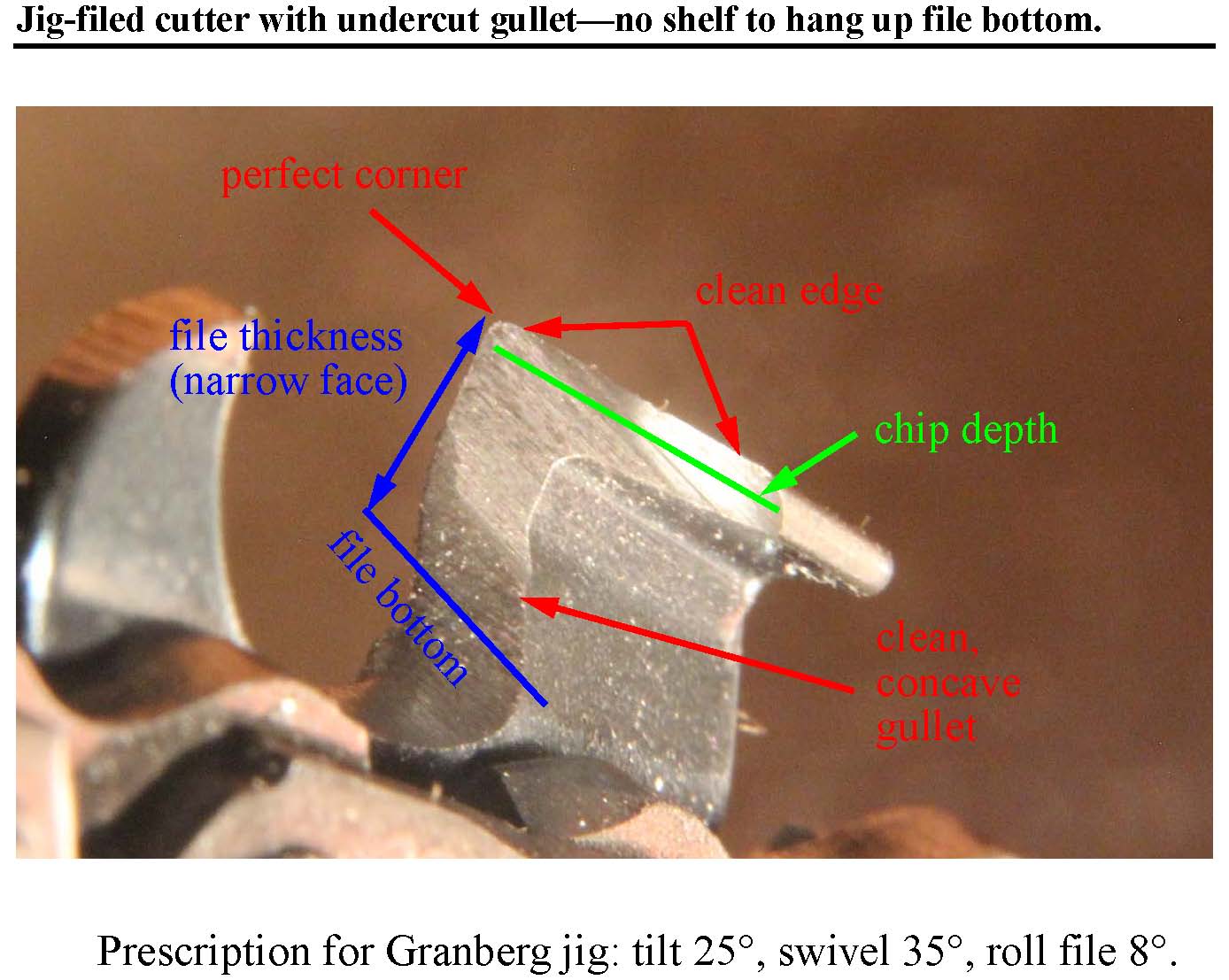
For full chisel (flat-filed) chain I recommend: 25 degrees tilt, 35 degrees swivel, and eight degrees up (toward the power head) for the bottom of the three-corner file. For hard wood perhaps four degrees up for the bottom of the file. See Fig. 8.
You can check the file position by looking for gaps all around the interface between the file and the cutter.
You can also test by painting the cutter face. I like a big red Marks-a-Lot. When think you have the alignment correct, give a light kissing stroke of the file on the cutter. Observe the scrape pattern in the painted face to determine any misalignment.
For my first cutter, I set the tooth length gauge (Part 17) so that it stops me after I sharpen the first cutter.
With tilt, swivel, and height correct, screw the depth gauge out until it just pushes the file away from the cutter. Now screw the depth gauge back in a bit so the file bites and sharpen the first cutter.
Begin counting cutters and proceed to the next cutter. If a subsequent cutter is too short to be properly sharpened, screw the tooth gauge in a little and start your count again. When you finally have your full cutter count, your last count restart will have been on the shortest cutter. The cutter lengths will even out more with each filing to reach an acceptable level.
When filing full chisel chain (see Fig. 3), I use up-filing on the right cutters and down-filing of the left cutters so the same face of the three-corner file is always toward the power head. Also, the handle of jig will always be on the right side of the bar. By this mean I do not need to change the roll angle when changing between right and left cutters.
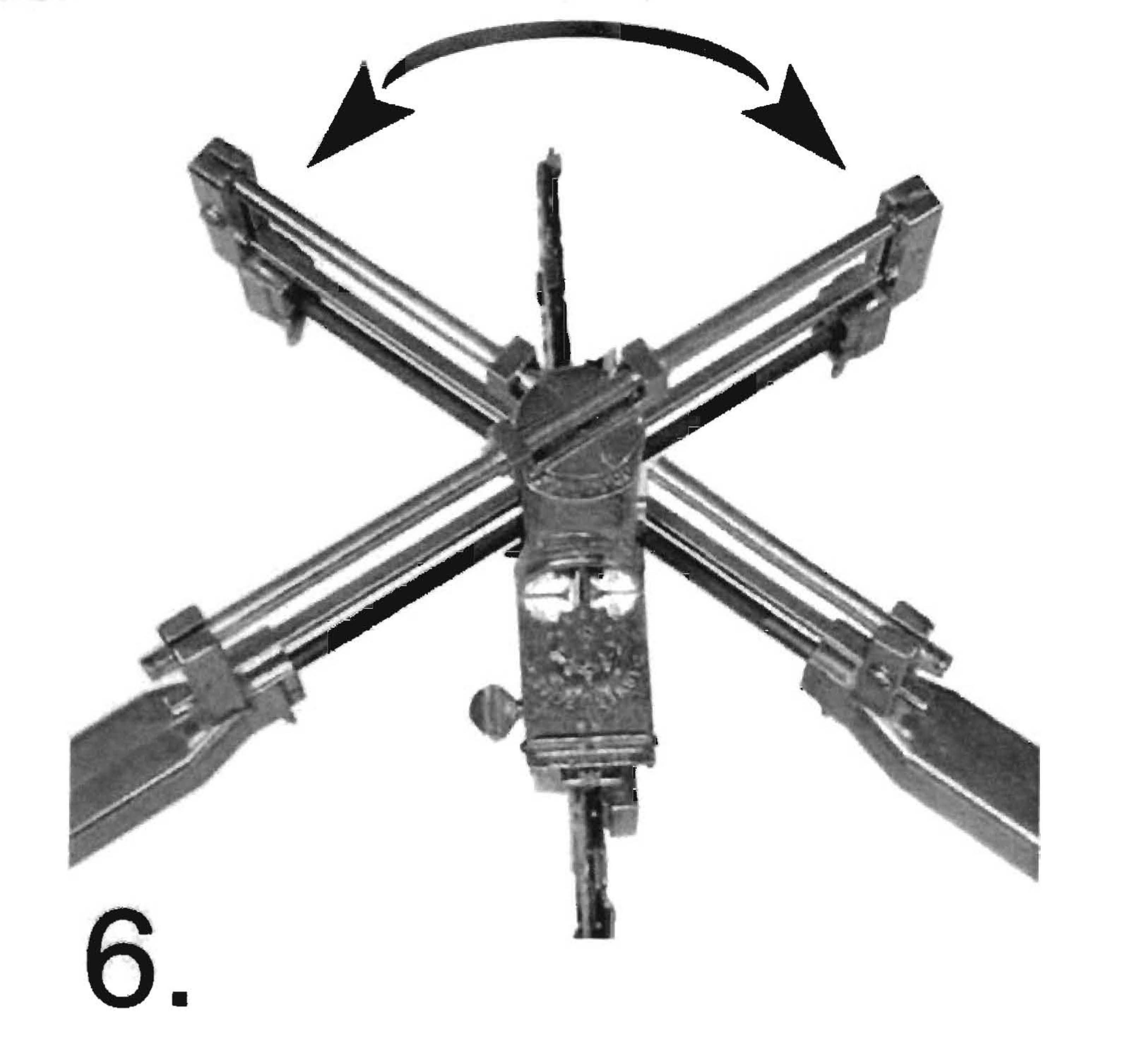
With up-filing of both sides, the handle crosses the back of the bar (power head side) to change sides. With down-filing of both sides, the handle crosses the nose end of the bar. Extracted image from the Granberg manual showing their recommendation for switching sides. Note that, as shown, working with the jig handle toward the power head employs the file as up-filing (inside-to-outside). Generally, down-filing (outside-to-inside) is better with the handle positioned toward the nose of the bar. Down-filing gives a slightly crisper feel, may require a stroke or two less, and will allow a dull file to be used a bit longer.
|
|
|
Extracted image from the Granberg manual showing their recommendation for switching sides. The right cutters are on the right side of this picture. Note that, as the jig is shown and with the file tang in the handle of the jig for safety, working with the jig handle toward the power head employs the file as up-filing (inside-to-outside). Generally, in opposition to Granberg's recommendation, I find down-filing (outside-to-inside) is better with the handle positioned toward the nose of the bar. Down-filing gives a slightly crisper feel, may require a stroke or two fewer, and will allow a dull file to be used a bit longer. However, I employ both up-filing and down-filing for full chisel chain so I do not have to reset the roll angle of the three-corner file when changing between right and left cutters. |
In contrast to the figure above, for filing full chisel chain, if we down-file the right cutters and up-file the left cutters, i.e. the jig handle stays on the right side of the bar, we do not have change the file roll angle when changing between right and left cutters. The roll angle will, of course, have to be reset after the three-corner is replaced after depth gauge filing which is often enough to adjust for the changing angle of the file holder frame.
If you are not using the lock nut as described in Fig. 13, you can still prevent jostling the tooth length gauge as follows. Let the file frame rest on the back of both hands, pinch the round head screw against the frame using your thumb on the head of the screw and second and third fingers of the same hand behind the frame. Using the index fingers of both hands, pick the thumb nut loose. Change the up-down tilt angle by rocking the frame over with the back of your hands. Pick the thumb nut back into tight position with your index fingers. A strange procedure, but with practice it can be done in a few seconds and helps to keep the left and right cutters to the same length without readjusting the stop screw, so it saves a fair amount of time. This was the method used in the youtube video. Replacing the spring with a lock nut makes switching side easier and a little faster.
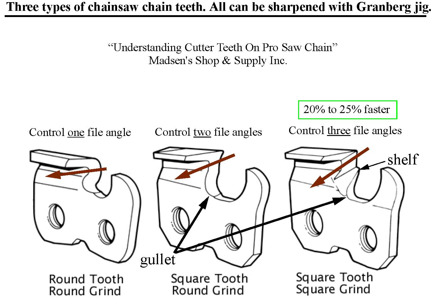
Fig. 1 shows a drawing of the three types of chainsaw cutters. This illustration is from a white paper by Madsen's Shop & Supply Inc., “Understanding Cutter Teeth On Pro Saw Chain”—an excellent discussion of chain sharpening. The drawing on the right side of Fig. 1 shows full chisel chain. The cutting surface is a true chisel shape, so in the rest of this review I will just call it chisel chain or full chisel chain. This cutter design is by far the fastest and gets dull slower than the round-filed, chisel cutters shown in the middle figure.
I believe full chisel chain has this advantage because the whole cutter edge is used efficiently. The cutter is actually a small chisel. Round-filed chisel chain depends too much on the point for cutting. Full chisel chain is tunable for soft or hard wood by making the chisel angle of attack shallower or steeper by controlling the file roll angle (Fig. 8) with the Granberg jig.
|
|
|
Fig. 1, A drawing of the three types of chainsaw cutters. This illustration is from a white paper by Madsen's Shop & Supply Inc., “Understanding Cutter Teeth On Pro Saw Chain”—an excellent discussion of chain sharpening.
Left figure: Round corner chain cuts slow but is very easy to sharpen as only one angle needs to be controlled. Center figure: Round-filed chisel chain cuts substantially faster than round corner chain. It requires control of the face plate angle and the departure from horizontal. Grinders, jigs, or hand filing can be used to sharpen. Gets dull relatively quickly as much of the cutting occurs at the outside corner of the cutter. Right figure: shows flat-filed, chisel chain also calls full chisel chain. The cutting surface is a true chisel shape, so in the rest of this review I will just call it chisel chain or full chisel chain. This cutter design is by far the fastest and stays sharp the longest. I believe full chisel chain has this advantage because the whole cutter edge is used efficiently. The cutter is actually a small chisel. Full chisel chain is tunable for soft or hard wood by making the chisel angle of attack shallower or steeper by controlling the file roll angle with the Granberg jig. See Fig. 8. Chisel chain is readily available from logging supply stores. Chisel chain and three-corner files are also available from mail order houses such as Baileys. For flat-filing, we will need a special hexagonal file universally called three-corner file. It has three wide surfaces and three narrow ones. I show pictures of one of these files in Fig. 7, 8, and 9. Once I learned to file full chisel chain with the Granberg jig, I never used any other type of chain. |
Round-filed, chisel chain (middle of Fig. 1) requires control of only two angles. Granberg provides dials to make this easy. File height determines the hook in the cutter shape. File height must also be controlled, although the tolerance is looser at about 0.010”. Because of the 10 degree tilt angle, this type of chain cannot be sharpened with one of the simple pressed metal file guides. Sharpening requires a jig or grinder.
Round corner chain (shown on the left in Fig. 1) only requires controlling the top plate angle. This chain can be filed with a pressed metal filing guide. However it is much slower than the other cutter styles.
Once I learned to sharpen round-filed, chisel chain; I never again used round corner chain.
Once I learned to file full chisel chain, I never again used round-filed, chisel chain.
With the Granberg File-N-Jig 106B you can achieve effectively perfect chainsaw chain. By "effectively" I mean no further improvement would have a noticeable effect on cutting speed.
Adjust the file height screw to get the hook correct. This adjustment only needs to be reset about as often as the depth gauges are done--usually after a full day of work--to account for the slow lowering of the cutter height as the cutters wear back (due to the top plate slope of about 10 degrees).
To set the file height with accuracy and repeatability, I use the excellent Granberg indexed height dial. Raise the file and move one of the cutters as necessary to put the bottom of the file directly above the outside corner of one of the cutters (round corner chain) or the inside corner for square chain. I then move the cutter back against the stop and lower the file by about 85% of the file height (add about an additional 0.015" for square corner chain because you are using the inside corner).
For 3/8", round-filed, square corner chain; I find 0.180" drop to be just right but dropping 0.185" gives too much hook. I cannot judge the difference of 0.005" by eye, but it makes a difference in performance, so I use the dial to get an accurate and repeatable setting. You will want to determine the exact height for your preference. Make sure that the full face of the cutter is filed, if the file is too low, the inside of the cutter may not be fully filed.
Flat-filed chisel chain, also called full chisel chain, is recognized by experts as the fastest chainsaw cutting chain with the further advantage that it retains its sharpness longer than the round filed chisel chain.
Use of full chisel chain has generally been limited to experienced professionals who either use one of the expensive, specilized grinders or have mastered the very difficult technique of hand filing the chain using one of the special files. However full chisel chain is easily and quickly sharpened in the field or at home with the Granberg jig as will be explained here.
Chisel chain requires that three angles be controlled. I will mostly use the names from the Granberg instruction manual and sometimes the part numbers:
1. Tilt: the off-horizontal angle across the bar. (Parts 20 and 16). In avionics this would be “roll”. Tilt is set to zero for round corner chain, and usually 10 degrees for round-filed, chisel chain. For full chisel chain, the tilt angle sets the balance between the top plate and side plate. To avoid hitting the links or chain clamps, the maximum tilt angle for chisel chain (also the best angle) is about 25 degrees.
2. Swivel: rotation forward and back toward the bar nose (Part 1, swivel guide). For other types of chain this is called the top plate angle, but all angles interact to some degree with full chisel chain. In avionics this is “yaw”. For full chisel chain, this angle primarily sets the chisel angle for the side plate, so the side plate is pretty good at cutting. The choice that best matches the factory grind for both Stihl and Oregon chain was 35 degrees.
3. File roll. Obviously file roll does not apply to round files. For the three-corner files this is the roll of the file in the v-shaped mount. The roll angle is very important as it primarily determines the angle of attack of the chisel cutter. Use shallower chisel angles for soft wood and steeper chisel angles for hard wood. The “hook” used with round-filing, chisel chain serves a similar purpose, but file roll is more directly effective for chisel chain. Although not an official feature of the Granberg jig, we can set and hold this angle accurately and reliably on the Granberg jig as I will describe. We will set the chisel angle indirectly by setting the bottom of the three-corner file relative to the swivel head joint.
The tilt angle and swivel angle are set with the dials provided by Granberg. The most convenient way to specify the file roll angle is by the angle of the bottom of the file relative to the swivel joint. See the discussion of Fig. 8. In addition to setting the three angles, the file height must be set very accurately so that the corner of the cutter has the proper shape. An accuracy of about 0.005” in height gives effectively perfect corners. This is easily done by aligning the ridge angles of the file and the cutter as shown in Fig. 9. I find best results by placing the file just a bit below ridge alignment. The chain clamps tend to settle down during filing and I must raise the jig a few times during work on each side.
|
|
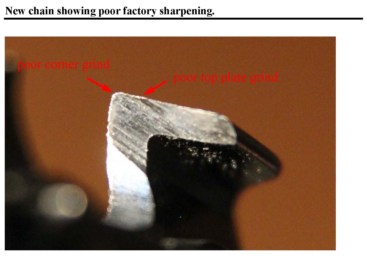
| Fig. 2 shows a cutter from brand new chain. Note the top edge and corner are not completely sharpened. This is the worst cutter on this particular chain. Even with some defects of this type this chain was serviceable right out of the box but was significantly improved by filing. The chain was Oregon 75CG105H, 3/8” pitch, .063” gauge. Mediocre factory grinds are common on other brands as well and new chain will frequently be improved by good filing. |
I have drawn a green line showing the approximate width peeled off to form the chip. Below that, the chip is peeling away past the gullet.
Note that the bottom of the abrasive wheel has created a shelf (or ledge) down near the links. We need to file out the shelf for new chain and after that from time-to-time by hand filing with a round file to form the gullet of the cutter. The gullet allows the chips to exit the cutting area.
Note the small marks on the link. The link is not significantly weakened by these marks, but they do establish that the grinder is working at about the maximum tilt angle allowed by the cutter design—about 25 degrees of tilt angle.
|
|
|
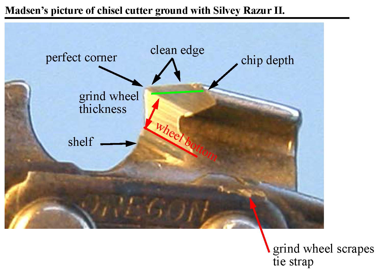
Fig. 3 shows a chisel cutter from the Madsen paper. Note the top, side, and corner of the cutting surface are filed completely; so they have achieved a very good cutter.
A green line shows the approximate width peeled off to form the wood chip. Below that, the chip is peeling away past the gullet. Note that the bottom of the abrasive wheel has created a shelf (or ledge) down near the links. We need to file out the shelf from time-to-time by hand filing with a round file to form the gullet of the cutter. The gullet allows the chips to exit the cutting area. Note the small marks on the link. The link is not significantly weakened by these marks, but they do establish that the grinder is working at about the maximum tilt angle allowed by the cutter design—about 25 degrees of tilt angle.
|
|
|
|
Fig. 4 shows a cutter that I sharpened with a three-corner file mounted in the Granberg jig. The top, side, and corner are completely sharpened. All the cutters look like this. (Please ignore small specks of dirt including one on the corner.)
Working free hand, I used a round file to create a smooth, undercut gullet. This deep, smooth gullet provides a clear path for chips to fly out of the cut. The undercut gullet prevents the bottom of the three-corner file from making a mini-shelf that may kick the three-corner file up to damage the corner of the cutter.
|
By using a round file to completely remove the shelf and leave an undercut, the bottom of the three-corner file never touches the cutter and leaves no shelf. We do not want the bottom of the file hanging up on anything: a shelf, the link, or the top of the chain clamp. When setting the file height, it is necessary to check that the file has free motion even when dropped slightly below the desired height. If the bottom of the file does bump on something it will kick up with the filing motion and cause a curve in the top plate.
The jig-filed cutter of Fig. 4 will perform as well as the ground cutter in Fig. 3. The jig costs $30 and may be used in the field, and I can leave the chain on the saw. My Silvey grinder cost $850, occupies space in my garage, and I have to invest time to swap the chain off and back on the saw. If you count swapping time, it will take me less time on the jig for a touch up. But if there is substantial dirt damage to the chain, then the grinder will have the advantage. I do not hit dirt very often, but if I do, I usually just take the necessary extra time to get the chain back into serviceable condition in the field by some extra filing.
When file sharpening, I take advantage of the fact that in normal use the chain is being filed back about 0.002” per hour (your results may be vary). When a dirt-damaged chain is brought into at least serviceable condition, I go back to work knowing that the chain will continue to improve in the next few sharpenings with the typical march backward of cutter length of 0.002” per hour.
There are no burs in Fig. 4, but burs do appear from time. They blow off in the first few seconds of cutting and do not degrade performance.
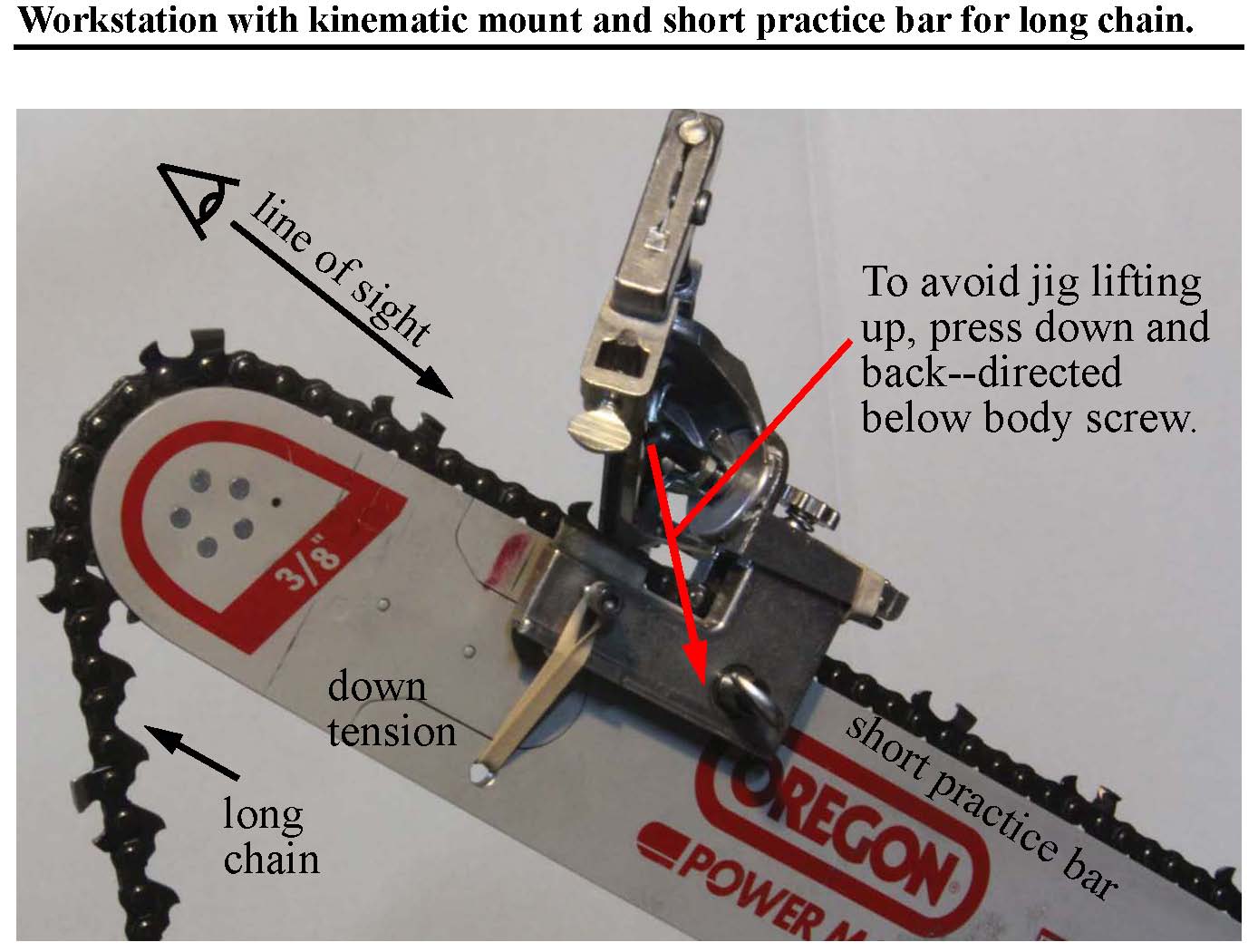
In Fig. 5, note that the chain clamps (actually chain guides) are riding on the tops of the rivets and that the jig is parallel with the bar. By riding on the tops of the rivets, the chain clamps prevent the cutters from rolling or lifting up during filing. Some grinders have hydraulic chain clamps to control the greater forces, but the forces typically exerted by filing are much lower and normally light downward pressure is sufficient.
With heavy dirt damage, you may want to really lean into your work. You can work in a standing position and set the saw on its bottom for solid support. Apply your pressure both back and somewhat down and into the bar so the net direction is just below the body screw (thumb screw, Part 11) as shown in Fig. 5. This will keep the upper carriage from lifting up and breaking your rhythm and perhaps ruining your alignment.
The chain shown is 32”, 3/8” pitch, 0.063 gauge, Oregon 75CG105H. The bar is only 20” but serves nicely for sharpening longer chain in a home setup. The upward angle of the bar allows a good view into the face of the cutters. Also, the chain moves smoothly without hanging up at the back where the sprocket is normally located.
|
|
|
Fig. 5 shows a setup using a short bar to hold a long chain--no need for a full length bar. The line of sight is back into cutter face so the cutting face can be easily seen. Pressing down as well as back on the file prevents the jig from lifting up.
This figure also shows a "chin strap" consisting of a rubber band through a drilled hole that helps to keep the jig pressing down onto the tops of the rivets. |
With a slight modification of the bar that will not degrade performance or safety, we can have a kinematic design that is very stable and does not distort the frame.
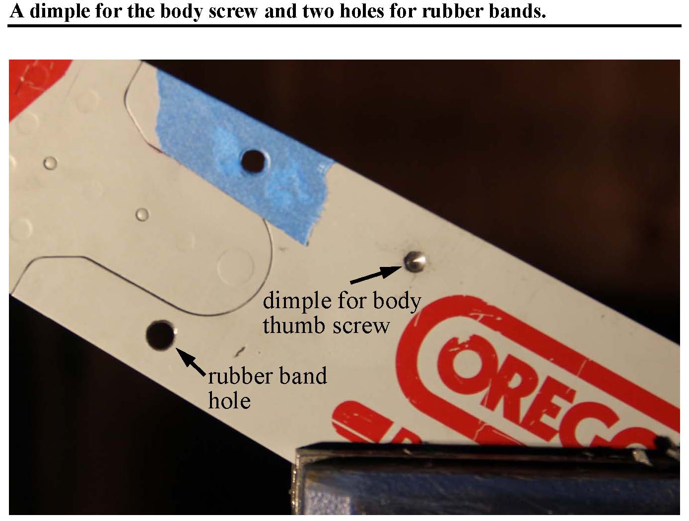
To stabilize the body screw I file the end of the screw round (a ball end) and put a conical dimple in the bar.
|
|
|
Fig. 6, shows a dimple made with a 3/16” Rigid, cobal, metal-cutting bit. The ball end of the screw seats accurately and reliable in the conical dimple. It is now easy to keep the jig level and at the proper height. I can take the jig off and put it back on and have exactly the same alignment. The jig will not slip down even with the bar coated with oil.
Also shown are a pair of 1/4" holes for a chin strap to give the jig some consistent downward pressure.
|
Fig. 6, shows a dimple made with a 3/16” Rigid, cobal, metal-cutting bit. The ball end of the screw seats accurately and reliable in the conical dimple. It is now easy to keep the jig level and at the proper height. I can take the jig off and put it back on and have exactly the same alignment. The jig will not slip down even with the bar coated with oil.
The chain clamps (actually chain guides) not only keep the jig at the proper height but prevent the chain from rolling or lifting up.
I like consistent, light downward pressure to pull the chain clamps down on the chain links. Gravity is not enough. This requires some sort of tension spring. With a 1/4” hole, I can use a Staples #64 rubber band looped through the hole and hanging on the chain clamp screws. To increase tension, take an extra turn around the chain clamp screws. I adjust the chain clamp spacing to achieve a height for the clamps giving smooth forward and backward movement of the chain.
If you make holes or dimples, make sure to choose your position carefully to avoid rivets and joints in the bar, and the raceway for the links.
Be prepared for the fact that the bar is fairly hard steel.
The V-shaped mount in the filing frame readily holds the three corner file over the angles necessary for flat filing. Note that the filing frame will vary in angle as the cutters wear back.
My preference is the Pferd 17081 three-corner file because it gives good surface smoothness and has the short sides at an appropriate width. The Vallorbe three-corner file does not have adequate width on the short sides for my taste. The Save Edge three-corner file produces a rougher surface than the Pferd.
For an expert discussion of the importance of edge smoothness, see Leonard Lee, Complete Guide to Sharpening.
|
|
|
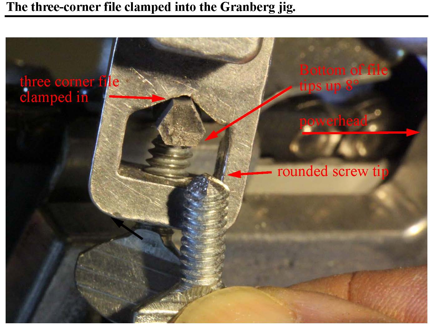
Fig. 7 shows a three-corner file clamped into the filing frame at a slight angle. The two upper edges of the file are both in contact with the V-shaped mounting surface. The mounting screws (Part 7) are 10-24, 1/2” thumb screws. I am holding another identical screw so the top of the screw may be seen better. I have rounded the screws off for better holding against the flat file surface, in similar manner to the rounding of the body screw.
The V-shaped mount in the filing frame readily holds the three corner file over the angles necessary for flat filing. Note that the filing frame will vary in angle as the cutters wear back.
|
|
|
|
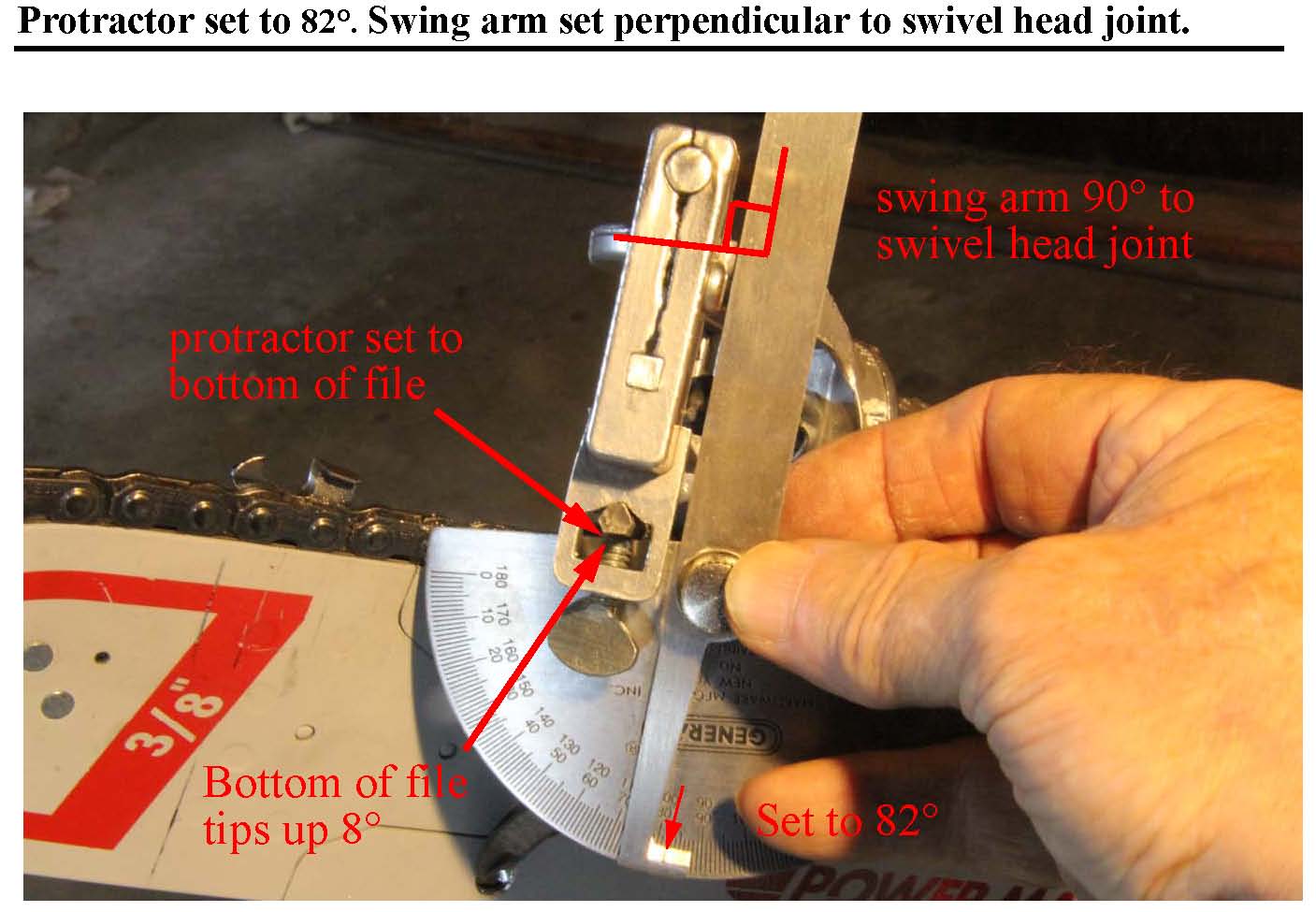
Fig. 8, I use a swivel arm protractor to set the roll angle of the file. The protractor is set to 82 degrees with the bottom of the file rising toward the power head. I set the protractor to have its flat side on the bottom of the file with the protractor in a plane perpendicular to the file. I then position the swing arm to be perpendicular to the swivel head joint. To make full use of all faces and corners, after wearing down three faces swivel the file 180 degrees and set up with the face of the progractor turned inward. Now you can wear the other side of the wide faces and the other three corners. This will double the life of the file. |
Although it is the upper and side surfaces of the file that are sharpening the cutter, it is more convenient to hold the protractor with the flat edge at the bottom of the file. In Fig. 8, I have preset the swing arm to 82 degrees (the bottom of the file rises toward the power head). I set the protractor to have its flat side on the bottom of the file with the protractor in a plane perpendicular to the file. I then position the swing arm to be perpendicular to the swivel head joint (Part 20).
I ignore the position of the file frame which will change as the cutters are filed back over the life of the chain. Because the file frame angle changes with cutter wear and carries the file with it.
When clamped properly, both upper corners of the file should be in contact with the V-mount as shown in Fig. 7. If I first tighten the front screw, as shown in Fig. 8, the file roll angle is set.
It is possible to lock the back screw askew, so the file runs out of alignment sideways. When setting the back screw, I then make sure to wiggle the file sideways to be sure the file has both corners in contact with the v-mount.
As shown in Fig. 8, the file is set up for up-filing of the left cutters. Up-filing has file motion from inside to outside the cutter. If we up-file the left cutters and down-file the right cutters, we can keep the same file roll angle when going from one side to the other and we do not have to reset the file roll angle each time. In this arrangement, when switching sides from left to right, the jig handle will stay on the right side of the bar and move from low, backward position for the left cutters to to high, forward position for the right cutters.
The file frame moves back toward the power head with cutter wear. For 3/8” chain you may get 0.3” of cutter wear, leaving only 0.1” at the end of life. The amounts to about 9 degrees of rotation of the file frame. The file sits in the frame but we want it to remain constant with respect to the swivel joint. Because of this it is necessary to reset the file roll angle for every day or two of use. If you are using the Granberg jig to set the depth gauge heights, you will need to reset this angle anyway after this task.
For hard wood, you may wish to try a shallower angle such as 4 degrees to increase the angle of attack of the chisel.
For grinding, both left and right sides should be ground downward (outside to inside). For filing, the performance of the cutter is the same for up-filing as down-filing and I find it impossible to distinguish the cutter method with a 10X loupe or by wear patterns after use. However, a dull file tends to skid with up-filing more than down-filing so I have to replace the file a bit sooner. For me the time saved in not resetting the file roll angle with each change of side is the deciding factor in using this combination of up-filing and down-filing.
The configuration shown in Fig. 8 will wear three of the six corners when rotated through the three wide faces. To use the other three corners and the other half of the three wide faces, the swivel head may be rotated 180 degrees and the angle set by flipping the protractor to face inward. The 180 degree swivel will double the life of the file.
Madsen’s paper discusses “beaks” and similar defects due to wrong file height.
It is best to check that the file does not vary in height during the stroke. If correction is needed, identify the low side, flip the frame up and use the three-corner file to work this end of the mount down a bit. The ridge angle of the three-corner file is 120 degrees. The angle of the v-mount is about 125 degrees, a bit larger than the file. On the three-corner file, you have one long side and one narrow side, so flip the file from side to side to alternate long and narrow sides to properly lower the 125 degree v-mount with the 120 degree file. This should preserve the capability to hold round files.
|
|
|
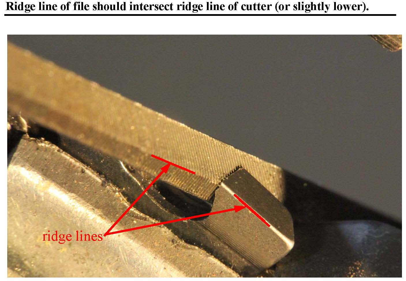
Fig. 9, the ridge line of the file should intersect the ridge line of the cutter between face and side plates (or be slightly lower). |
|
|
|
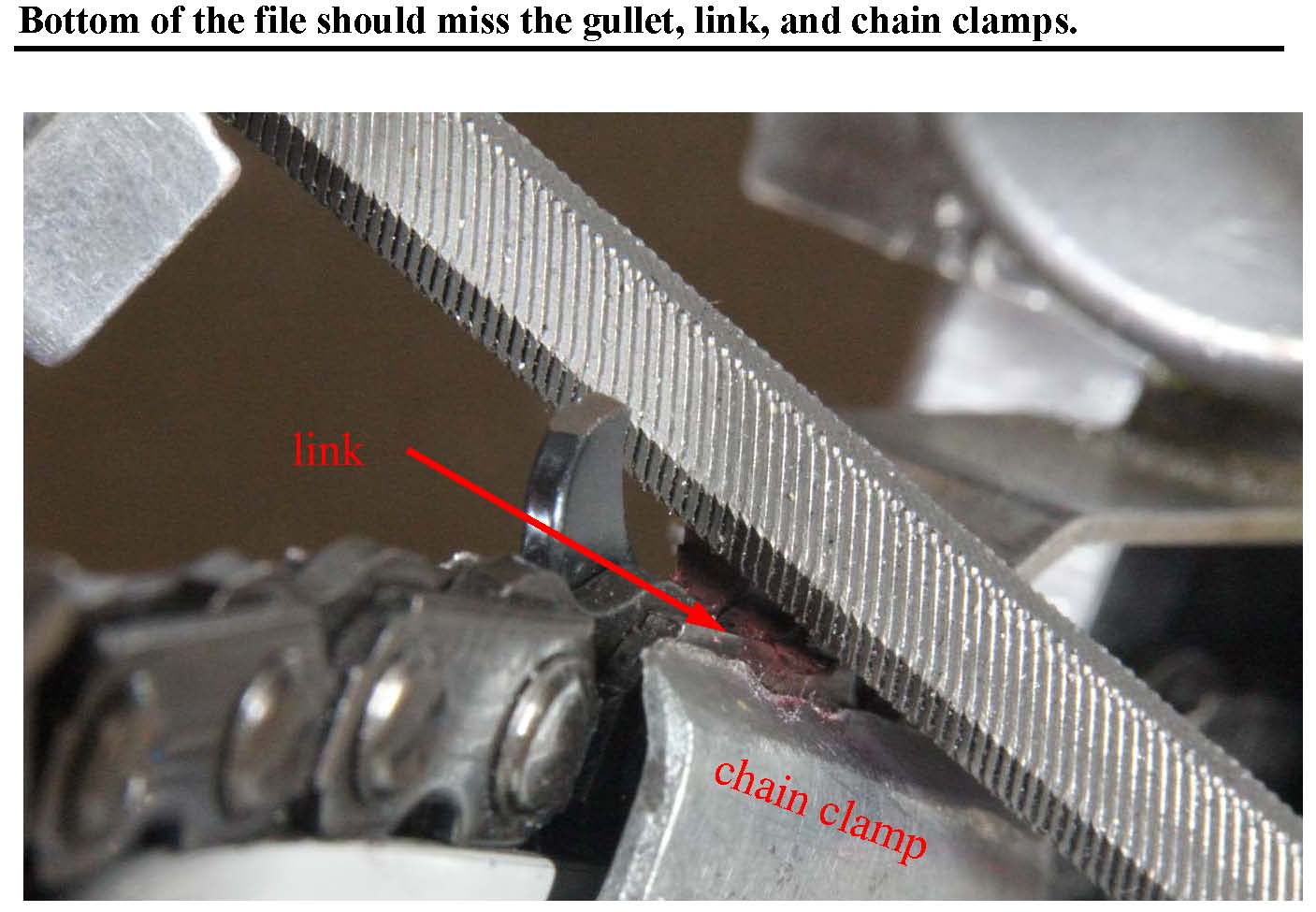
Fig. 10, it is shown that the bottom of the file is clearing the link and the top of the chain clamp. To avoid the file kicking up, keep the bottom of the file from hitting anything. |
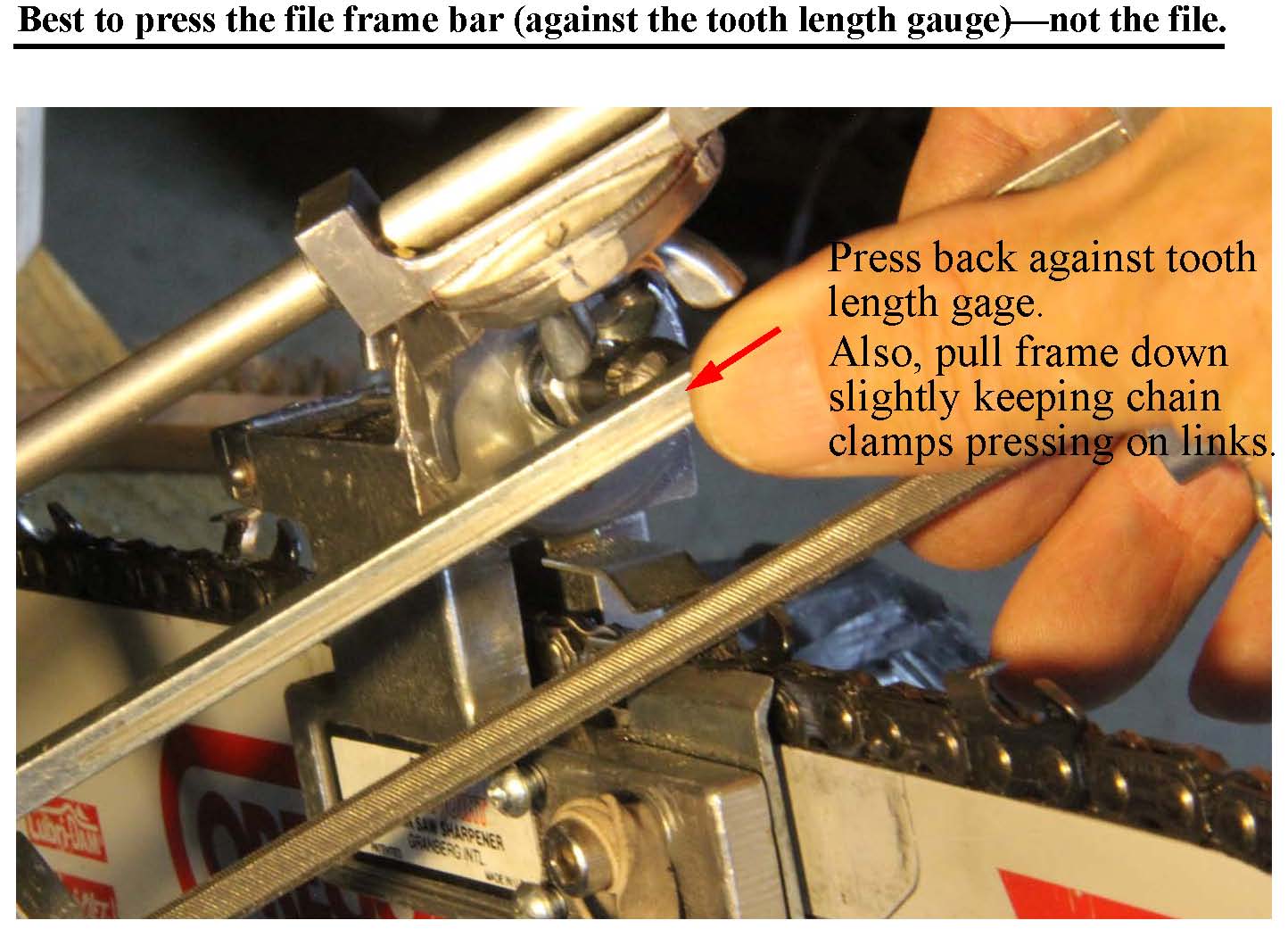
For best accuracy push the file frame bar (Part 4) against the tooth length gauge (the screw, Part 17), as shown in Fig. 11. With this method the frame is not bent.
I made a test with four cutters, measuring each of the four cutters three times with a digital caliper:
1) pushing on the file directly: .343”, .338”, .347”, .343”, avg .3428”, root mean square = .0032”
2) pushing the file frame bar into the tooth length gauge: .330”, .333”, .329”, .334, avg .3323”, root mean square = .0021”
Of course, either way the error is small.
|
|
|
Fig. 11 shows my thumb pushing the file frame bar (Part 4) against the tooth length gauge (the screw, Part 17). With this method the frame is not bent. |
I can use my thumb on the front of the round head screw and two fingers opposing on the back to pinch the round head screw while changing the tilt, but this is somewhat awkward.
|
|
|
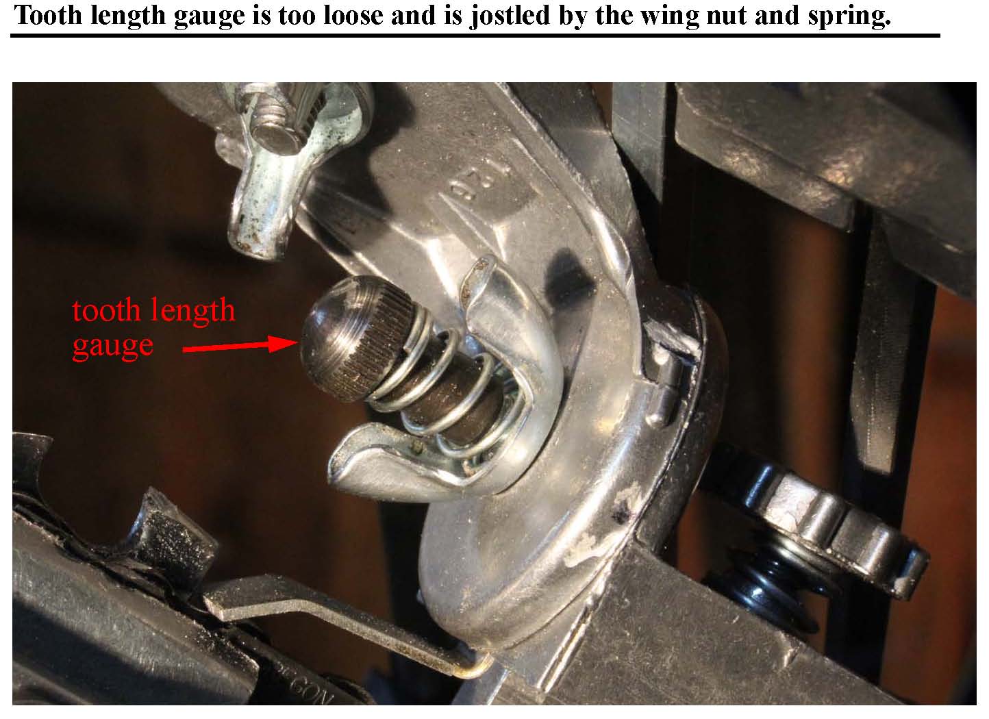
Fig. 12 shows the tooth length gauge (Part 17)—the file stop. The round head screw is too loose. It flops around, especially in the extended position used for chisel chain. Also, when the wing nut is loosened to change the tilt, the round head screw tends to rotate with the wing nut because of the spring connecting them. We lose our reference point creating problems in keeping the left and right cutters the same length. |
I have to work without gloves to adjust the lock nut. Usually I work without gloves as my hands have learned to avoid the front of the cutters. I just pinch the sides or push the back.
Rotation of one face of the lock nut gives about 0.010” of file movement, so we have a nice measure of the file position for face-to-face rotation. Using both faces and points on the hex nut, we get a precision of 0.005” in file movement.
I use the lock nut as the primary control of depth. I move the nut counting faces or perhaps faces and points. I then twist the round head screw down onto the lock nut, so really the tooth length gauge is the lock nut.
|
|
|
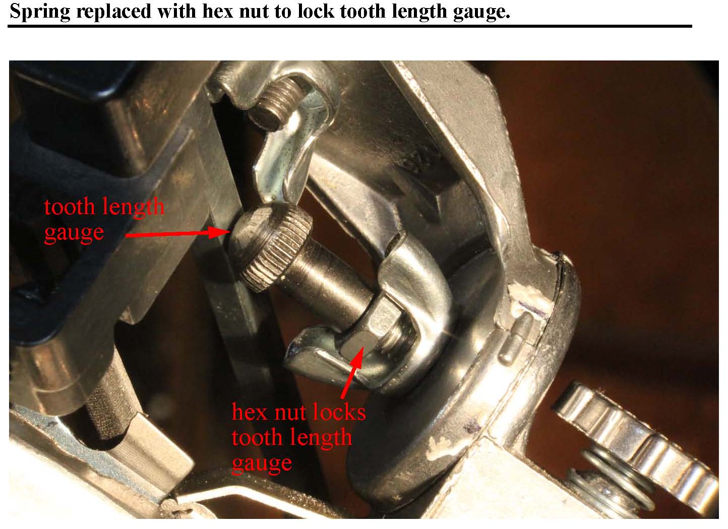
Fig 13 shows an improved mechanism. The screw has been removed and replaced with a 10-32 hex nut as a lock nut. The tooth length gauge is now supported quite solidly and loosening the wing nut does not disturb the length adjustment as the spring is gone. |
Generally, I can judge centering by just looking for even spacing between the chain clamps.
The jig seems to be designed for the greater thickness of longer bars.
For my home work station, the 20” bar is noticeably thinner than my 32” bar and I wanted to have a correction capability for the jig that so I could use the same jig on both thin and thick bars.
Fig. 14 shows the inside of the bottom of the jig and the method of centering the bar. Two pads shown hold the back of the bar opposing the force of the body screw. I filed down the inner pad (near the chain clamps) somewhat and replaced its function with two tapped 6-32 screws coming in from the sides. I can now control bar centering over a good range. Also the two screws, when adjusted properly, provide a more secure back stop for the body screws preventing sidewise wobble.
|
|
|
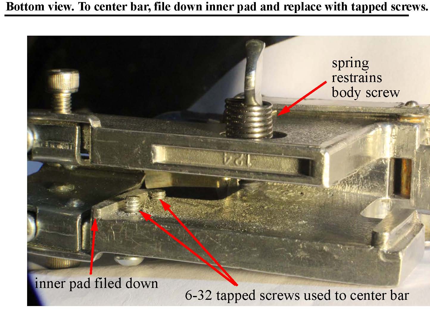
Fig. 14 shows the inside of the bottom of the jig and the method of centering the bar. Two pads shown hold the back of the bar opposing the force of the body screw. I filed down the inner pad (near the chain clamps) somewhat and replaced its function with two tapped 6-32 screws coming in from the sides. I can now control bar centering over a good range. Also the two screws, when adjusted properly, provide a more secure back stop for the body screws preventing sidewise wobble. |
For a 32” bar and 35 cutters of chisel chain with the bar mounted in a vise, I have a top speed of just under four minutes to give an average value of just under 7 seconds per cutter. I figure a 1 second penalty for real chisel chain over round-filed, chisel change due to the need to check on the file height every five or six cutters with full chisel chain and to occasional tweak of the height.
Holding the bar free-hand with the power head resting on the ground (steadied by feet) adds about 2 or 3 seconds per cutter relative to mounting the bar in a vise. A reasonable top speed for flat-file chisel chain, hand-holding the bar is about 10 seconds per cutter for a light touch up (no significant dirt damage) done in the field.
I note that my 32” skip chain has 18 cutters on one side and 17 on the other--a six percent difference. The chain runs fine and the cuts do not curve.
When I start filing, I look carefully at the cutting surface of the first cutter, adjust the tooth length guage (Part 17) to file appropriately and start my count. If I encounter a significantly shorter cutter, I move the tooth length gauge in and start my count again.
One full rotation of the stop screw corresponds to about 0.060" of file movement, so usually a small bump is all that is required to update the stop screw position. Using the lock nut, I have a precise measure of length change.
If you are using the lock nut, the tooth length gauge will not be jostled when changing the tilt angle from side to side.
Caution! Never lower the depth gauges more than a couple of strokes without making test cuts. Be especially cautious when using a new, unfamiliar method such as this jig. Test with a down cut, up cut, and bore cut. The chain will become aggressive and hard to control if the depth gauges are too low.
The depth gauges must be lowered at least as fast as the cutter heights drop. If the gauges are not lowered your chips will become thin and cutting speed will fall off. Irregular depth gauge heights contribute to vibration with a corresponding loss of cutting power.
The cutter top plate has a 1:6 slope front-to-back. If the cutters have lost about 0.012” or 0.018” of length (about a full day's worth of chain wear for me), they have lost about 0.002" to 0.003” of height, and it might be time to lower the depth gauges. With the jig, it takes me about nine minutes total to file both the depth gauge heights with the jig and to file the slopes of the depth gauges in the usual free hand manner.
The best depth gauge file to use is the Pferd 4130, EDP 17051, 8" x 23/64" x 15/64" flat file. This is a replacement depth gauge file for the Pferd Chain Sharp file guide, but happens to work perfectly in the Granberg jig. It is also possible to use one of the three-corner files. I have not found a triangular file with both zero taper and the necessary accuracy.
To set the jig up for depth gauge filing, adjust both the tilt angle and swivel angle to zero. You need to have the bottom of the file parallel to the bar. If you have a swing arm protractor, you can set the depth gauge file to about 89 degrees (file bottom angles up slightly toward the power head), place the protractor on the bottom of the file and the swing arm perpendicular to the swivel head joint similar to Fig. 8.
In any case, check the file roll by verifying that with the file just resting on the depth gauge, moving the chain back and forth under the file will cause even scraping all the way across the bottom. Now raise the file with the height screw and set it down gently on one of the cutters. Note the dial indication and then lower the file by the depth gauge setting for your chain, often 0.025”. I may use 0.030” for a slightly more aggressive chain.
The depth gauge file may vibrate in an annoying manner. On some chains, the depth gauges have distinct left and right forms and you may find the file vibrates more according to the direction. If so, do all the depth gauges on the side that vibrates less. Then flip the file end-for-end and do the depth gauges on the other side.
Dirt trick 1. In the field, I can get maximum filing force by putting the saw on its butt to get solid support. I hold the nose with my non-filing hand to steady the bar and control the chain movement. Only a shop vise gives stronger support.
Dirt trick 2. To get full force on all strokes, using your non-filing hand on the nose roll the chain just a bit to get the cutter off the back stop, so it is not supplying any back pressure. Without the help of the backstop, all your file pressure will now go onto the cutter. To check progress, roll the chain back against the stop and make a stroke or two to check if your file is finally starting to lose its bite.
For round-filing, moderate dirt damage requiring about 0.005" to 0.015" to be filed off, one can use the Granberg Grind-N-Joint Bar Mounted 12 Volt Chain Grinder with a diamond bit. It mounts in the same way as the Granberg jig and gives a cutter shape very compatible with the round file used in the jig. The diamond bits keep their shape and give a cleaner surface than other bits.
But usually I just file away with my regular setup.
If you tend to have a lot of dirt damage, you may need a chain grinder.